-How
To Choose the Correct Stepped Attenuator Value. General Rules and
Considerations: -How
To Choose the Correct Stepped Attenuator Value. General Rules and
Considerations: |
1)-When
upgrading from a potentiometer, use the same value stepped attenuator.
(5K,
10K, 25K, 50K, 100K, etc.)
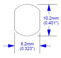
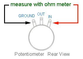
If you need
to find the potentiometer value by measuring it:
1) Unplug the equipment from any AC source.
2) Unsolder two of the three wires going to one channel of your
potentiometer. (It does not matter which two wires.) |
 |
| 2)-Matching
the volume control value to the amplifier/pre-amplifier input impedance
is not as important as some people think, so you typically don't really
have to worry about this. For a 100K
input impedance, use a 100K, 50K, 25K, or even a 10K level
control. This applies to passive preamps, active preamplifiers, and power
amplifiers when the control is to be installed at the Input. Check your
owner's manual to find the the rated Input Impedance of your unit, or
contact
the manufacturer directly. Our 25K stepped attenuator usually value
replaces replaces 20K potentiometers. |
| 3)-Regarding
the choice of stepped attenuator values in Goldpoint SA1, SA2,
SA4
(25K) and SA1X, SA2X (10K), much
observation and thought has gone into this over many years. We
concluded
that the values which we are using for our standard off-the-shelf
passive
preamps and precision level controls should not
be changed (unless really necessary or preferred for some other
reason).
Lower stepped attenuator values make
them
more compatible with a wider range of power amplifier Input impedances
- which they might encounter
over time. |
|
Notes:
One common
opinion states that with the higher
value level controls, such as 50K and 100K, you can hear higher
amounts of (desirable) high frequency harmonics, or even that "it
sounds
more open and airy". A similar opinion states that the lower
values, such as 10K and 25K sound
slightly "richer" or "more full bodied". The actual truth may depend on
the equipment being listened to and/or which set or ears is doing the
listening.
I have found that the stepped attenuator (volume control) value is
usually
not so critical - and that it does not make as much difference as some
people
claim - but that other aspects of the equipment or system can make
bigger,
more noticeable sonic differences. |
| There
is a common misconception that higher value volume controls such as 50K
or 100K will result in LOUDER sound compared to using 10K or 25K volume
controls. This is not true. 10K controls usually yield exactly the same
loudness as 100K units. (Technically, there are other reasons why
different
value controls are used in different places or applications.) |
| Vacuum
tube equipment often uses 25K, 50K,
or 100K level controls, due to the high input impedance of
tubes.
Solid-state gear usually has 10K, 25K,
or 50K level controls. |
| You
can begin to have "high frequency roll off" beginning to appear with
volume
control values above 100K. If you don't have an engineer handy, or just
can't decide,
25K is a good choice
for both vacuum tube and solid-state equipment, especially for passive
level controls. |
| We use the
25K
stepped attenuator value in our home audio (RCA connector) SA1, SA2,
and
SA4 passive preamps. Our balanced (XLR connector) SA1X and SA2X
precision
level controls use 10K stepped
attenuators
- as this level control value is common in the Pro Audio environment. |
| Actually, you
can also use a stepped attenuator value which is HIGHER
than the rated input impedance - this doesn't really hurt anything -
they are essentially just voltage dividers! So
don't worry about it if that's what you end up with. The sound quality
will typically not be noticeably affected. |
|
Goldpoint
Standard stepped attenuators of any value will always sound better
than
potentiometers -
due
to the transparent sonic quality of the Thin Film Nichrome resistors we
use on them.
|