-How
To Install Goldpoint 24-Position Stepped Attenuators and Selector
Switches: -How
To Install Goldpoint 24-Position Stepped Attenuators and Selector
Switches: |
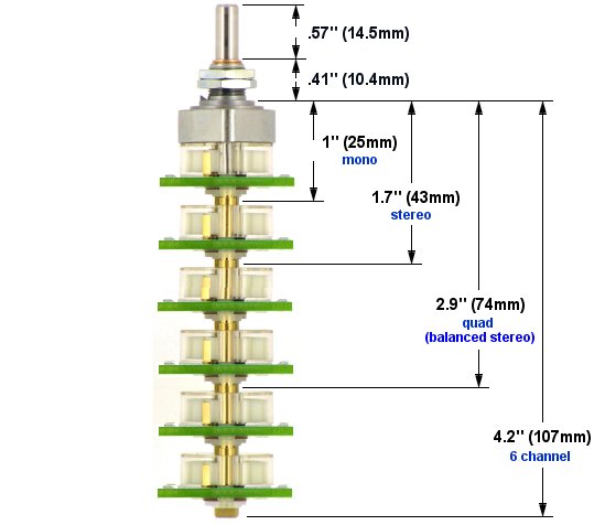
| The front metal sections
of Goldpoint 12 and 24 position rotary switches were ingenuously designed in Switzerland
or Germany around 1960. A protruding, pointed tab (labeled "Locking Key"
below) was
employed as an anti-rotation feature. This works great, but entails a
little bit more attention to mounting these units on a panel than
simply drilling a hole and tightening a hex nut. Very
Important! The
most common error made when installing one of these units is to fail
to: |
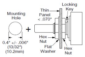
| 1) Use a second hex nut inside the mounting panel - as shown in Mounting
Method #1. |
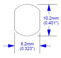
| 2) Or cut or file a channel (keyway in the panel) for the locking key to
fit into - as shown in Mounting
Method #2. |
3) Or file off the protruding locking key - Mounting
Method #3. This is usually OK because our audio stepped attenuators and selector
switches have a lot less turning torque than the original switches in
the 1960s, so you don't really need the locking key now. (While filing
off the protruding key, clamp the switch shaft (only) in a large,
stable vise.)
|
|
|
| Mounting
Method 1:
If the panel you are mounting to is thin: up to 0.07", (1/16"), (1.5
mm),
you can mount the unit using two hex nuts and a flat washer. This is the
preferred and easiest mounting method. |
| Important:
Never
allow the tip of the locking key to touch the inner hex nut - doing so
could warp
and damage the unit. |
|
|

|
|
|
|
| Mounting
Method 2:
If the panel is thicker than 0.07", up to 0.255" (6.5mm), mount the unit with only one hex
nut
and a flat washer. Make
a notch in the mounting
hole - as shown at left under "Mounting
Hole with Keyway". |
| Important: Never
allow the locking key tip to touch the inside of the mounting panel -
doing
so could warp and damage the unit. |
| Mounting
Method 3: File
off the protruding locking key - whether the mounting panel is thin
or thick. Mount in round hole, no notch, with one or two hex nuts and a
flat washer - as
shown at left. Before filing, wrap the rest of the unit with kitchen
plastic wrap to ensure the filings do not get into the switch
contacts. |
|
|
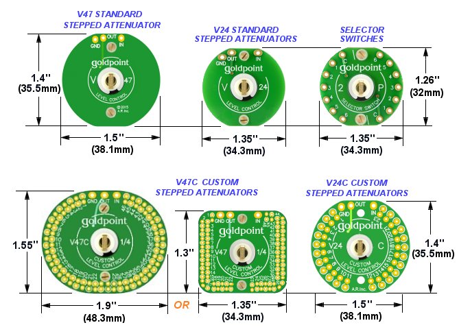
Mounting
Hole for Goldpoint
47-Position Stepped Attenuators:
|
 |
Our
47-Position stepped attenuators use a "Double-D"
panel cutout as an anti-rotation feature.
However, because
our rotational torque is fairly low, you can simply mount them into a
round hole (diameter = 0.401" or 10.2mm).
If you use a round hole, place a lock-washer on the threaded
bushing before
sliding it into the front panel or put a flat washer under the hex nut on the outside of the front
panel.
Maximum panel thickness is about 0.255" (6.5mm) if you mount the attenuator with a hexnut and one flat washer. |
|
|
| Mounting Data in Acrobat PDF file |
|