|
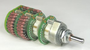
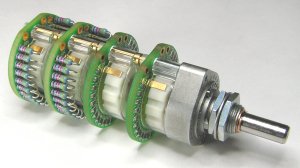
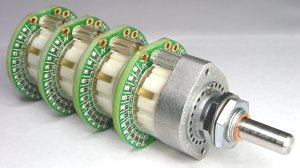
Goldpoint
attenuator
replacement for a McIntosh C20 preamplifier.
The first
step in this ‘endeavor’
is to have on hand the schematic for the Mac C20.
One source is
Sams Photofact
#475 folder four. I believe the McIntosh company will also sell
you
a schematic for the C20. Another source is
http://www.vintageaudiomanuals.com/search.htm
The next
step is to determine
the C20 model that you are working on. The early model has a
brass
bar across the front panel ands the volume control does not have a
cover
over it. I replaced the attenuator on an early model. See
if
the unit does work. Now unplug the C20 from the power
source.
Remove the
knobs, front panel,
and the plastic indicators on the top row of switches and pots. Remove
the bracket holding the two lamps that surround the volume
control
shaft.
Now, the
hard part. Remove the wires from the volume control. Mark where the wires
go.
I found that new coax has to be installed from the balance pot
and
the mode switch. Note the location of ONE of the ground
wires.
It SUPPLIES the ground to the control and also two resistors under the
chassis. This ground wire comes from the front circuit board. Cut
the power leads going to the power switch on the old control. Now
remove the old control.
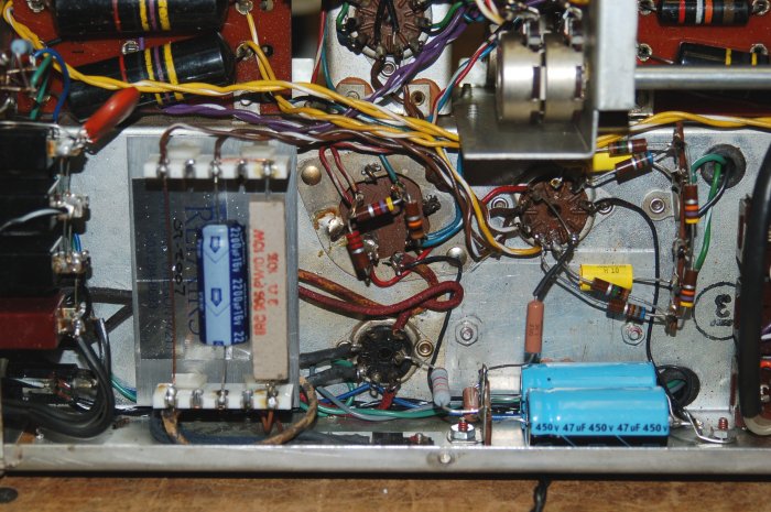
Since the
Gold Point attenuator
is longer than the original control, the electrolytic capacitor (C1 in
the Sams) behind the control will have to be relocated. I added
an
insulated solder terminal and a ground terminal on the inner side of
the
chassis, right under the old location of C1. I had to drill
a couple of holes in the side. I used two 40 mfd @ 450 vdc caps and
rewired
them according to the schematic. I covered the hole with an
aluminum
plate mounted from the bottom of the chassis.
Since
I was
under the chassis,
I replaced the filament rectifiers and its 2000 mfd capacitor. I
used a dual positive center rectifier assembly equivalent to NTE 6086.
Use the hole the old rectifier terminal strip to mount the
rectifier assembly. A couple more terminals where the old 2000
mfd
cap was located, and you are operational.
You could
used the original
grommets in the chassis, but I found the original ones very hard.
I replaced all of them in the attenuator area.
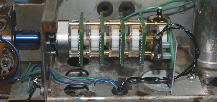
The
mounting hole for the
attenuator will have to be enlarged. The Gold Point
attenuator
will be mounted using both nuts that are furnished. A coupler is
required for the Gold Point – C20V modification. The
coupler
fits between the chassis mount and the lamp bracket. The
couple
is drilled for 1/4 inch shafts and the Gold Point shaft is
metric. A single layer of black plastic electrical tape will take up the
slack. Make sure the solder points on the Gold Point are facing
up. A shaft extension with a flat for the knob will have to be
manufactured.
I imagine you could cut the shaft off from the [old] control.
(Goldpoint
offers a shaft coupler which you can use here. See: bottom of
page: http://www.goldpt.com/prices)
I also made
a bracket to
hold the rear of the switch. I used the mounting screws for the
power
switch to attach the bracket to the switch and one of the holes that
held
the original FP type capacitor.
Now, to
wire the attenuator. The first thing is to twist some #22 stranded wire and run it form the
AC receptacle to the power switch on the Gold Point.
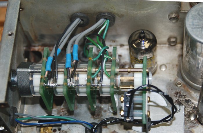
Run a #20
solid wire through
the four grounds on the printed circuit boars of the switch and solder
– CAREFULLY!
Do
the coax
first. The coax is grounded at the switch and NOT at the balance
control.
I always like to add a short piece of shrink tubing to the ends of the
coax. You will need to cover the ground shields at the switch
with
shrink tubing. Note that the rear balance pot center tap goes to
the front 100K printed circuit plate ’in’ terminal. The ‘out’
terminal
of the front plate (A) goes to the mode switch ‘single’ terminal. But
you know that since you marked the wires and cables. The (B)
output goes to the terminal with the wire jumper.
The final
wiring is from
the AURAL COMPENSATION pot (center tap) to the ‘in’ terminal of the C
plate
and ‘D’ plate. At the same time you have these wires to replace,
replace the ground wire from the from PC board to the ground buss on
the
switch.
Run the
‘out’ wires from
the one meg plates to the correct capacitor inputs under the
chassis. Note that there is a ground wire from the junction of two 47K resistors
that has to be run to the ground buss on the attenuator.
You are
about done. After connecting inputs and outputs, power on the preamplifier. You
will note, assuming you made no errors, there is a click when the
attenuator
is rotated. This is the make break of the switch contacts.
I do not know if there is a fix.
The last
‘suggestion’ is
to make a cover plate over the switch to help keep little fingers from
the power switch and deflect the spillage of beverages into the Gold
Point
attenuator.
written
by: Robert
Walters - (503) 284-8693 - email: caiman.ss323@comcast.net
4105 N.E.
Alberta Court,
Portland, OR 97211
|