|
Goldpoint
Selector Switches
|

|
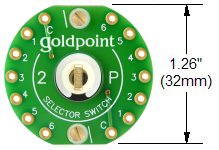
Goldpoint
selector switches were designed for high quality audio applications. |
|
|
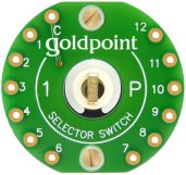
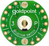
They
are easy to use. Each switch position is clearly labeled on both sides
of the PC boards,
"1,
2, 3", etc., and the common (pole) connections are labeled "C". |
|
|
RoHS
compliant. |
|
All
Goldpoint selector switches have 30 degree switching angles. This means
that each knob position will point 30 degrees away from its adjacent position(s).
(Our 24-position stepped attenuators have 15 degree switching angles -
each adjacent knob position.) |
|
click
here or on images for dimensions
|
|
|
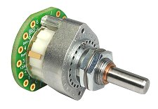
|
single deck
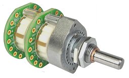
|
dual deck
|
|
|
|
(you can specify
/ order these selector switches with as many as 6 decks)
|

|
4
different switch decks with different circuit configurations are available: |
|
ALL Goldpoint selector switches
are 30 degree switching angle. |
|
|
 |
 |
 |
 |
|
|
|
|
1P
1
Pole (1 circuit),
and
up to 12 Positions
(per
deck)
|
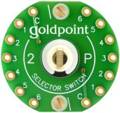
2P
2
Poles (2 circuits),
and
up to 6 Positions
(per
deck)
|
3P
3
Poles (3 circuits),
and
up to 4 Positions
(per
deck)
|
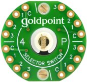
-4P
4
Poles (4 circuits),
and
up to 3 Positions
(per
deck)
|
|
|
|
|
|
|
|
|
|
|
|
|
Part
Numbers: |
|
|
|
| More
example part numbers: |
| 1P-8T-1D
= 1 Pole, 8 Positions, 1 Deck |
| 2P-6T-1D
= 2 Poles, 6 Positions, 1 Deck |
| 3P-4T-1D
= 3 Poles, 4 Positions, 1 Deck |
| 4P-3T-1D
= 4 Poles, 3 Positions, 1 Deck |
| 2P-6T-2D
= 4 Poles, 6 Positions, 2 Decks (2 Poles per deck) |
| 2P-5T-3D
= 6 Poles, 5 Positions, 3 Decks (2 Poles per deck) |
| 4P-3T-4D
= 16 Poles, 3 Positions, 4 Decks (4 Poles per deck) |
|
|
|
|
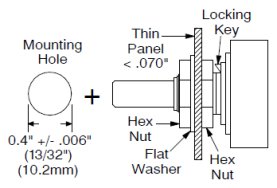
A
second "Stop Screw" is used to set (or change) the maximum number of switch
positions.
Never
move the first stop screw (the one installed at index position "0").
see
illustration below |
|
|
|